Cleaning all the parts and inside suiface of shell before assembling, then:
(1)Insert the bladder by pull Rod;
(2)Install the name plate and lock nut on gas valve side;
(3)lnsert the oilvalve and then the rubber coated retaining ring;
(4)Locate the oil valve on to support ring fit gaskets and spacerring, then tighten the lock nut and making sure the assembly is centrally located;
(5)Fit the bleed screw with gasket;
(6)Finally mount the gas valve,then tightens again the lock nut.
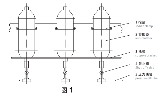
To achieve a high degree of efficiency, the accumlator should be fixed as close as possible that is severs lt is recom mendedthe accumulator should be installed vertically; the same time adequate space is necessary for and filling equipment.
Correct fastening is given using clamps and brackets arranged as (fig.1)
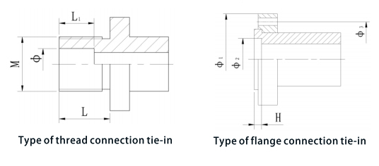
The thread connection tie-in can see the table-2. Flange connection tie-in can seethe table-3. Please note the tie-in connected with the oil-in valve should be wringed the Suitably dimension to avoid to damage the bladder.
The accurate choice of pre-charge pressure is fundamental in obtaining the optimum efficiency and maximum life from the accumulator and its components, the maximum storage or release of liquid is obtained the oretically when the gas pre-chargepressure is as close as possible to the mininmum working pressure.
For practical purposes to give a safety margin. and to avoid valve shut off during operation, the valve, unless otherwise stated, is=0.9.
Special valve are used for:
(1)Hydraulic line shock damper.=0.9.To keep constant pressure, re-charging is necessary when the gas pressure lower. In the same time, It is very important to find the reason of gas leading and to replace in time.
When the accumulator stopped working, it is necessary to shut off the ball valve between the accumulator and the pressure pipe for keeping the hydraulic circuit pressure overgas pressure in the bladder.
(1)For the reason of gas valve, replace the gas valve after discharging completely the gas from the bladder by gas charging kit.
(2)For the reason of seal ring between the gas valve and bladder, replace it after discharging completely the gas from the badder by gas charging kit.
(3)For the reason of bladder damage, replace it after discharging completely the gas from the bladder by gas charging kit.
ln any case, if find any leaking of hydraulic oil, replace the o ring between the oid fluid valve and adapter.
First, the accumulator must be cut off and discharged from the liquid pressure and removed from the hydraulic ircuit, after that place the accumulator horizontally in a vice then proceed, for both the types,as follows:
(1)Remove the protection cap of gas valve and discharge completely the gas from the bladder by gas charging kit then dismantle the gas valve;
(2)Remove the lock nut, name, plate;
(3)Remove the gas valve;
(4)Remove bleed the bleed screw;
(5)Remove thelock nut and spacer ring;
(6)Push the oil valve into the shell and remove gaskets;
(7)Bend the rubber coated retaining ring and remove it from the shell;
(8)Remove the oil valve from the shell;
(9)Remove the bladder from the liquid side by slightly twisting.